| Hacking a Mouse for parts |
||
| Did
you know most cameras (digital) can see infrared? I new this from
reading on the internet, but filed it away, as I had no immediate need.
Today I used that tidbit. I need an opto-isolator for a project. You'll see why in a minute! I am using an Arduino microcontroller to control 120 VAC (Standard household voltage in the USA). I am testing it with a desk lamp, but it will eventually be used to run a 150W cartridge heater. Since I have a bag of triacs in my junk box, I wanted to use one. It drives with a low voltage signal of 1 or 2 volts DC and switches the AC. In case you don't know, a triac requires a signal to be applied to keep an ac load energized. Without the signal applied, the ac will shut off when it passes zero volts. If you used a triac to try to switch DC, it would latch and never turn off until the dc went away. 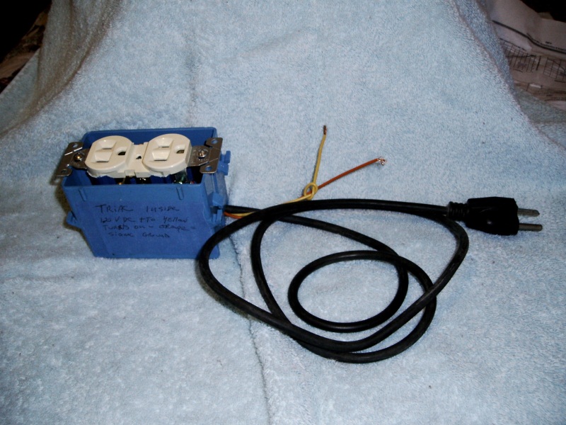 Encouraged by this small success, I wired up the Arduino with a couple of resistors to make a voltage divider to drop the 5v by about half. I used the Blink example sketch from the Arduino IDE to pulse a different pin (#9 IIRC) and watched it blink an led on a breadboard to make sure it was working. I turned it off by removing the USB cable that was powering it, removed the led and installed the resistors and hooked it up to the triac. I plugged in the USB from my quad-core desktop computer to power the Arduino... BAM! Bad smell!! I unplugged everything while cussing. I tested everything individually. Everything worked except for a jumper wire with alligator clips and one of the resistors crisped. The jumper acted as a fuse. How lucky was that? I figure that somewhere under the desk, in that jungle of power strips, the hot and neutral got crossed and the USB ground provided a circuit. So, now I need an isolator. I have an old mouse I took apart to investigate the encoders. It uses an optical pair to provide light for the encoder wheels to interrupt. I cut the board to isolate the components and wired up the led side (with its resistor still onboard) to 5v from the Arduino. Nothing. I reversed the wires, still nothing. Then I remembered they might be infrared. I dug out my digital camera and Wala! By looking at the led trough the viewfinder on my digital camera, I can see a dot of IR. 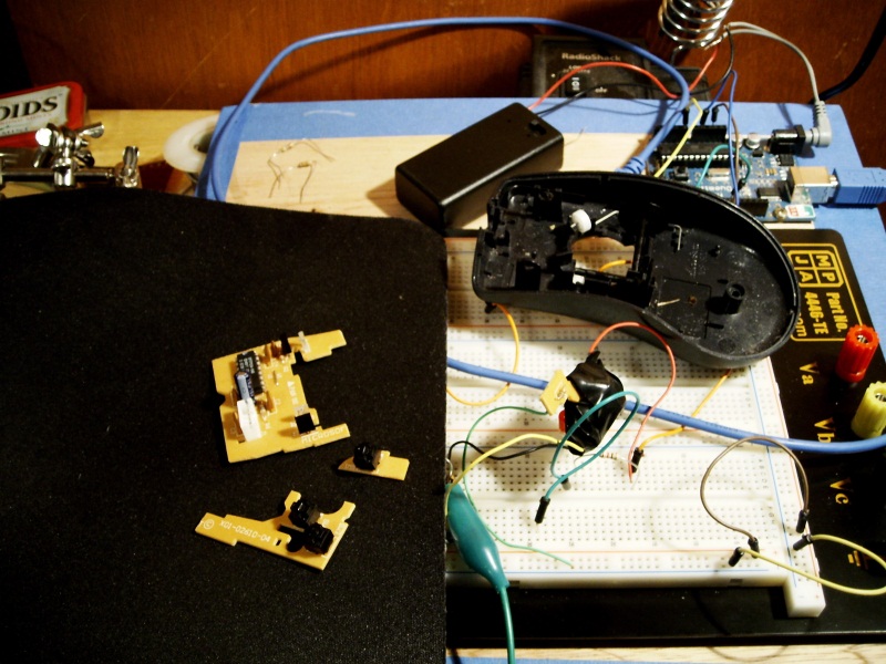 Now I need to hack the detector side. it has three leads and looks for all the world like a transistor. Hmmm... I Googled around and finally found a site that shed some light on the subject. It turns out the detector is a pair of detectors, photo diodes to be exact. The center lead is the V+ and the outer leads pass this voltage when in the presence of light, but not in the dark. With the emitter lit, I measured almost all of the 5 volts applied (4.7), but some may have been dropped along the way in connections and what not. It works just as well with lower voltages. I tried 1.2V and 2.4V from my rechargable ni-cads and it all worked. What threw me for a time was I was getting erattic results. It would conduct when I thought it shouldn't. Then I realized shadows made a difference. I needed to block the room light! It was then that I discovered not everything worked to block the light. It seems a lot of stuff is transparent to different wavelengths. I wound up wrapping the pair in several layers of black electrical tape. After that, I was able to get predictable results. The remainder of the mouse still has several hackable parts, as well. I salvaged two more of the emitter detector pairs. These are great for encoders, as in robotics projects. I think the dual detectors will output quadrature signals just by the physical placement from a single emmiter. Be sure to save them intact on a chunk or the board so you don't lose the placement relative to each other. Remember, if you make an encoder wheel, not everything is opaque to IR. The plastic in the original encoder wheels are. I also kept three push button switches that could be used for limit switches on a cnc machine or bump detectors in a robot. There are several capacitors and resistors as well as a small 5 position plug and socket on the PS-2 cable. |
||