My CNC Adventures!
The journey begins...
by
Ron Thompson
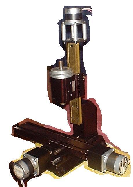
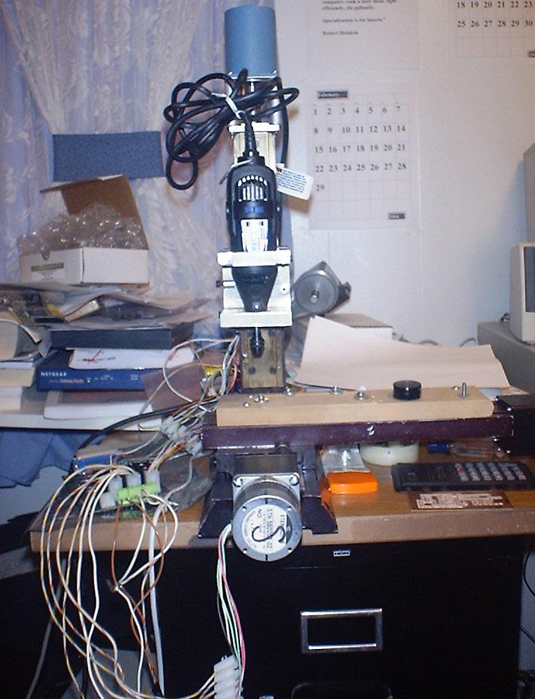
I bought this used, motorless Sherline mill and added steppers.
While the 60 oz\in motors in the picture above were OK for the X and Y axes, the Z axis needed more. I upgraded to 100 oz\in and now it moves OK.
My old digital camera doesn't do too well in low light conditions (like indoors), but I think it's good enough to convey the details. Scroll down for more pictures.
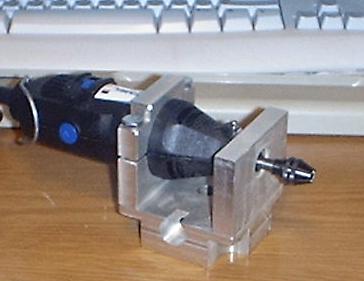
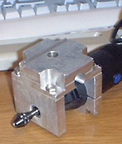
Since I didn't have a spindle drive motor, I used my Nichols mill to make a mount for my Dremel model 275.
I used my $20 Harbor Freight Digital Calipers (a good item, by the way) and measured the Sherline spindle housing. Whenever I had a small discrepancy of a few thousandths from fractional measurements, I used the fractional. For example, if I measured .310", I assumed it to be 5/16" (.3125")
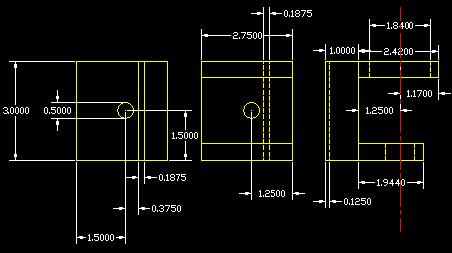
I drew it in CAD and took the drawings to the shop. The cad drawings look much better than this.
Material is aluminum. My base block is 1" thick and the other parts are 1/2" thick. I modified the countersinks to fit the 1/4-20 fasteners I had on hand.
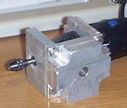
The "nose" thread on my Dremel was measured to be 3/4"-12 RH. I mounted the lower plate in a 4 jaw chuck on my Monarch lathe and threaded it with a boring bar. When I screwed the Dremel in, it didn't seat well. I cut a small counterbore at the entrance to the thread, and now it seats.
I measured the body of the Dremel as 1.84"ø. I bored this in the upper plate on the lathe, then moved to the mill and cut the height of the corners to fit my fasteners, drilled and tapped the holes, and then cut it on the bandsaw to separate the cap.
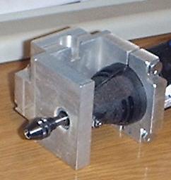
The only critical dimension on the 1/2" thick parts is the centerline of the Dremel to the base block. This needs to be the same on both plates for the spindle to be truly vertical.
The setscrew in the side of the base block is .6875" (11/16") from the mounting face and is centered on the 1/2" bore (1.5" from the bottom).
On the pictures below, you can click the image for a larger version.
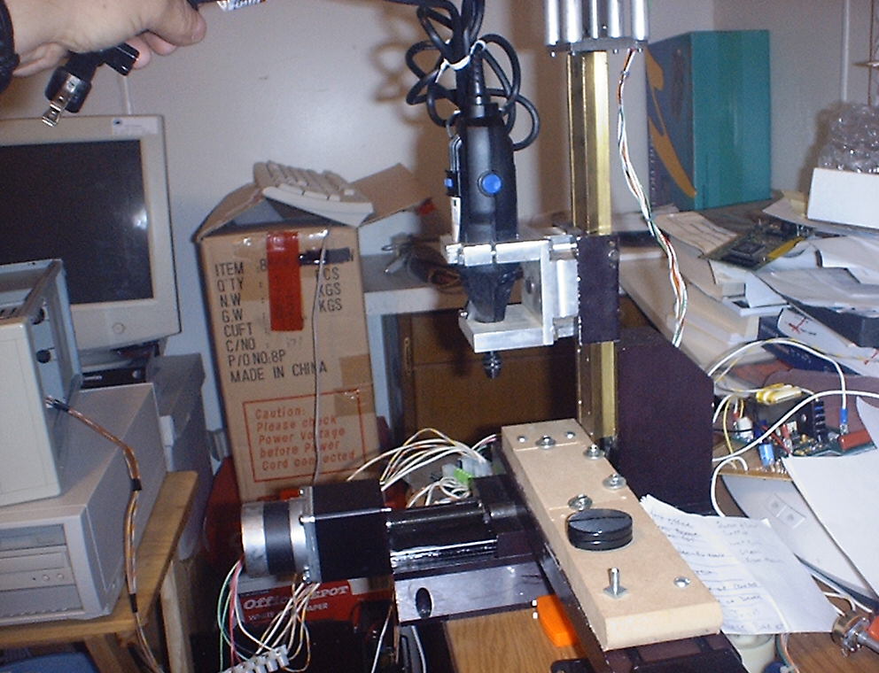
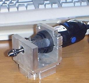
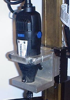
After all this, I managed to cobble together a variable speed spindle motor and mount. It's ugly, but it works. The motor is from the beater bar of a Compact vacuum cleaner. It's a universal motor, so it doesn't mind running on PWM DC from the speed control board. That is the speed control behind the mill in the right picture, above.
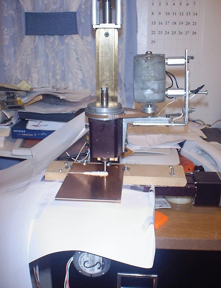
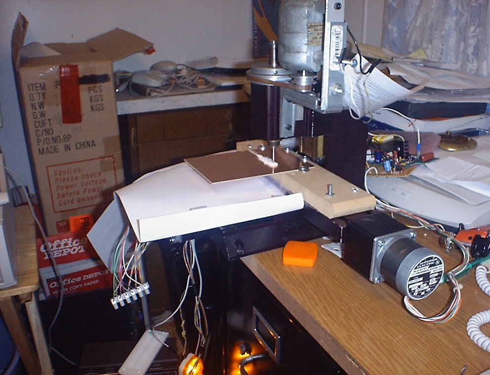
Finally, a real project, not just working on the machine! In the pictures above I am cutting a circuit board to size. The light at the bottom of the right picture (above) is to remind me to turn the power off to the steppers when they aren't running.
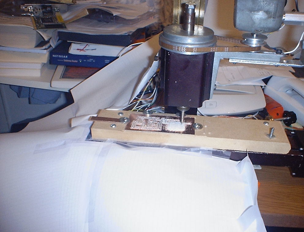
In this shot. the board is clamped to the MDF "tooling plate" with sheet metal screws and washers. The board is positively located via a depression milled into the MDF. The endmill is 1/16" and proved to be a little to big for the traces to come out right. But, hey, that's what prototyping is all about, finding the boogers and fixing them.
By the way, the mill is running. The camera flash stopped the belt for the shot. The paper is taped around the table to prevent chips from killing the bare driver board and the bare speed control board.
I haven't set any backlash compensation in TurboCNC, but the endmill drops right back into the previous cuts. I was impressed!
That's all for now.
Ron Thompson