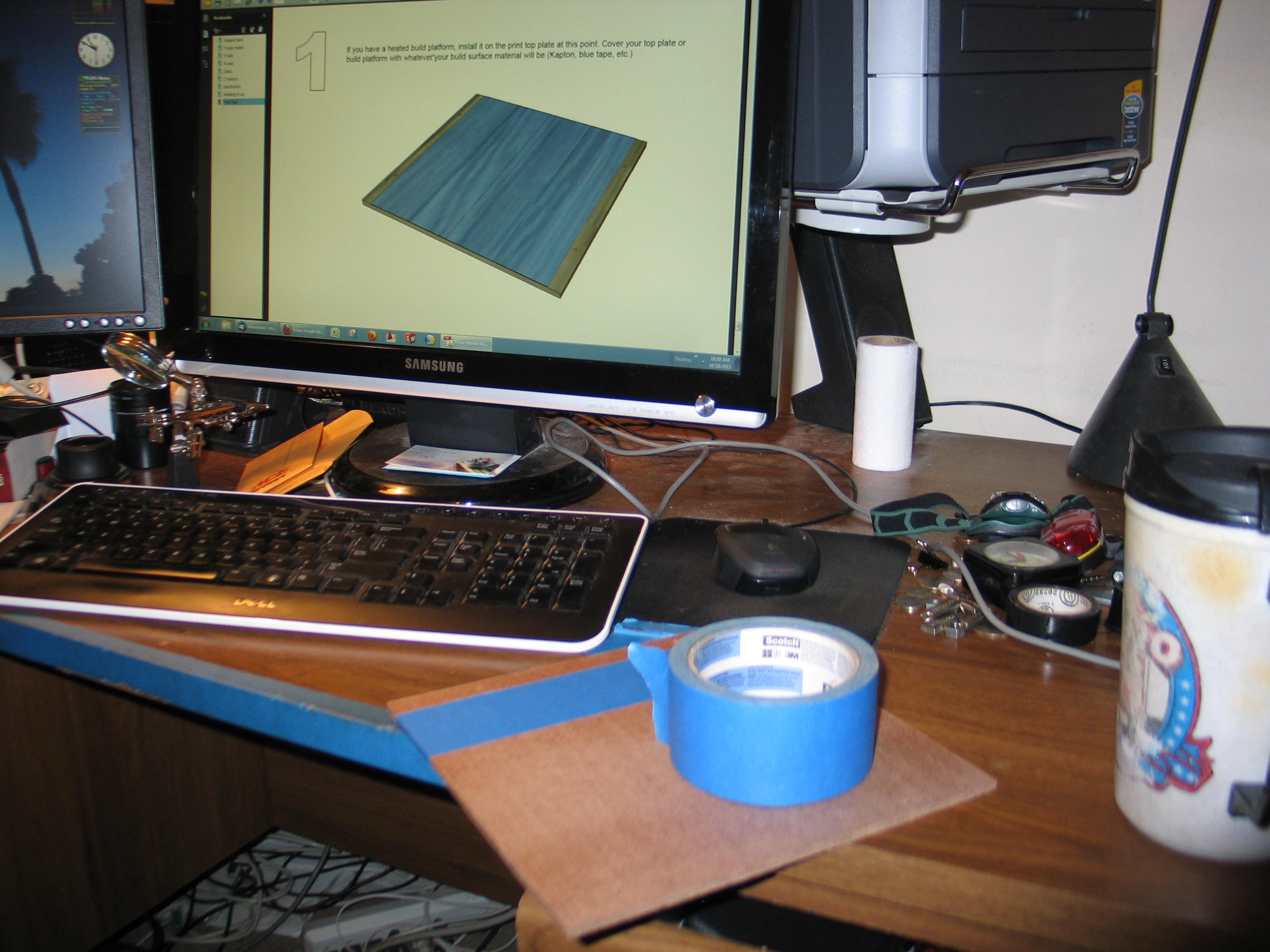
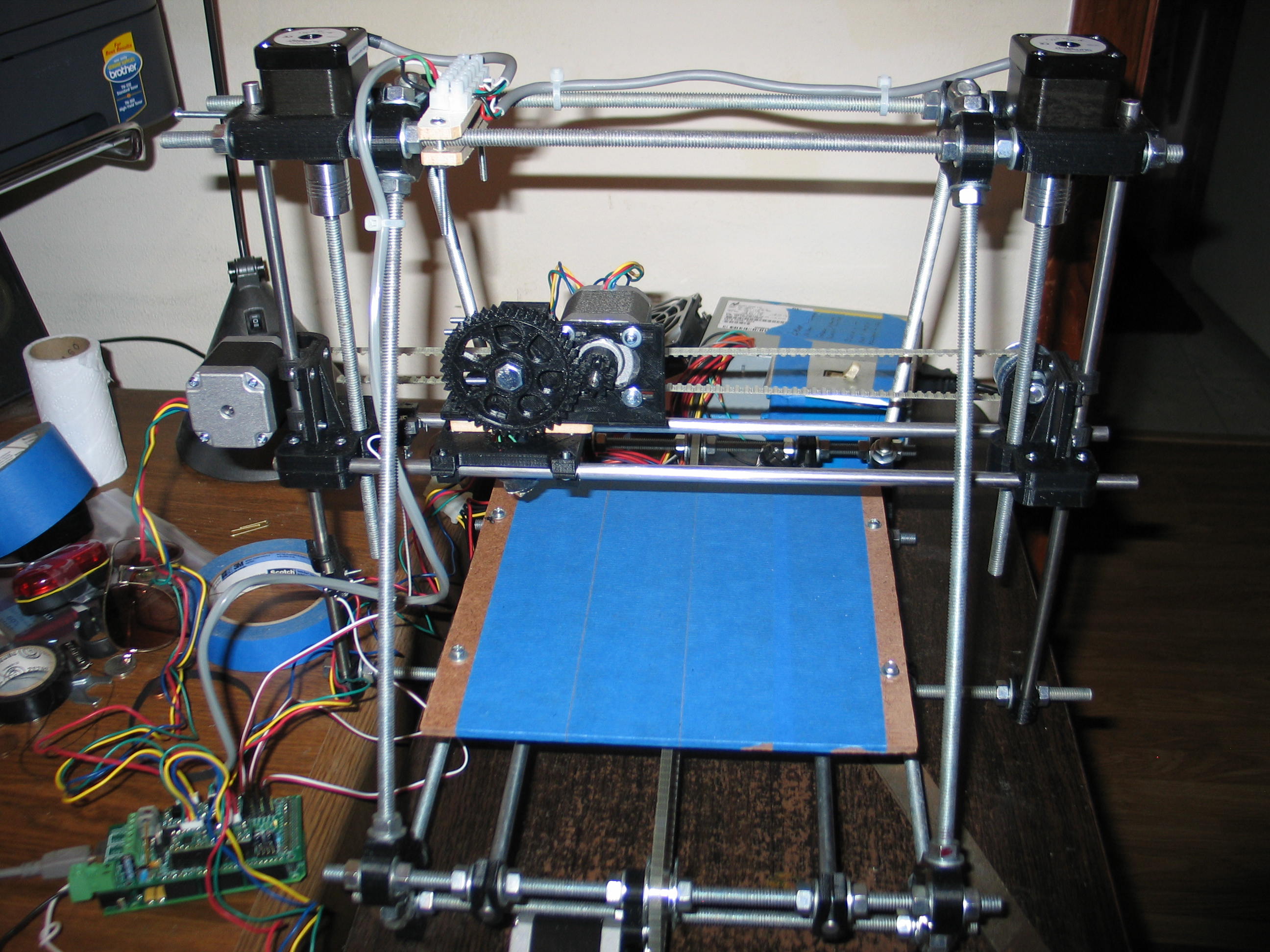
Next up, adding the build platform. I don't have a heated bed, as yet, so I opted for the blue tape. This worked out for me because I use it on my CNC router for holding down foam to be milled. In case your wondering, I mill foam for lost foam foundry patterns.
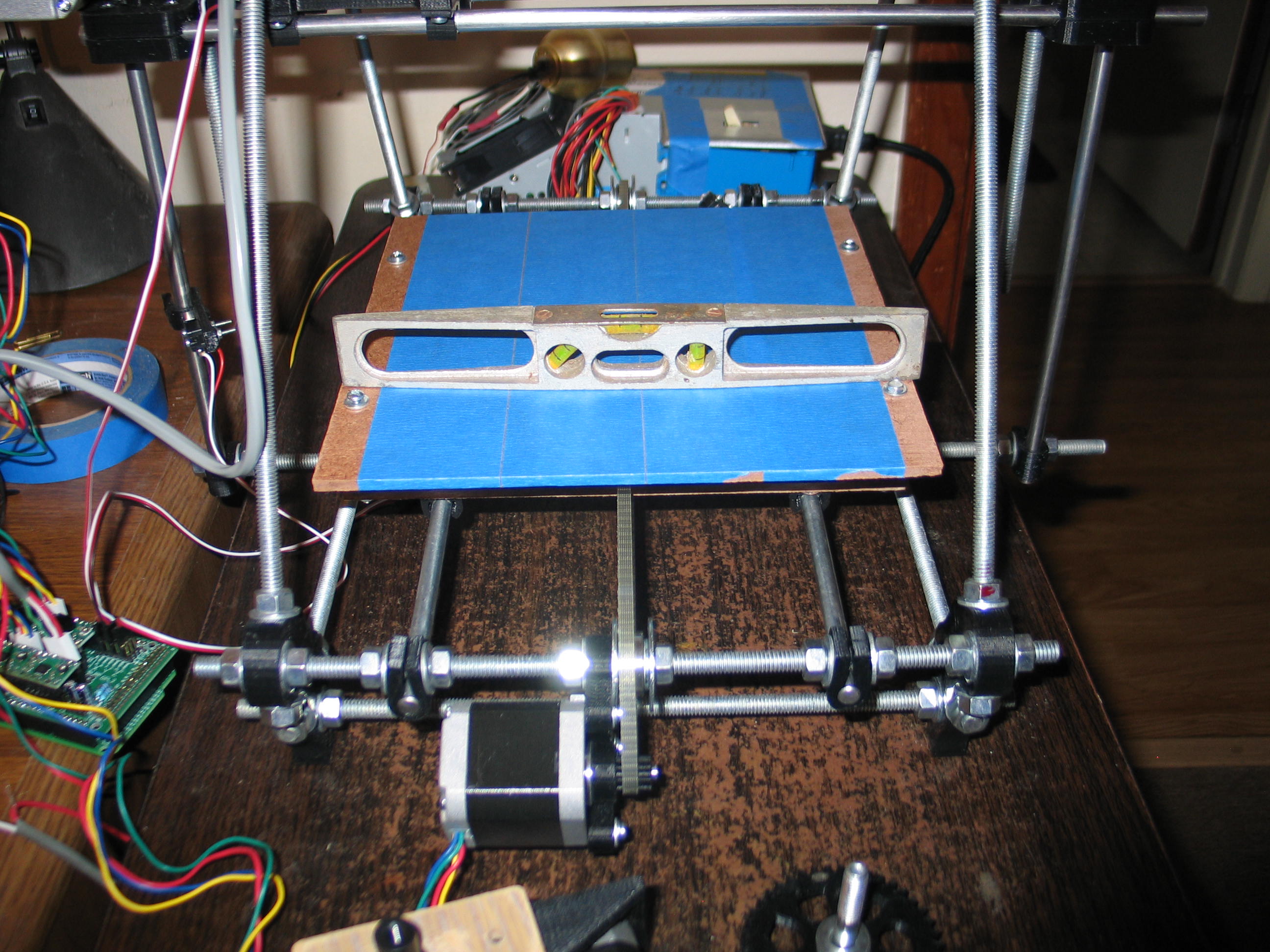
I put the level on the table
in front of the 3D printer and noted the bubble position was just to
the right of center. I then leveled the build platform to the same
offset in the bubble.
Then I did the other direction the same way.
That was too easy! I must have screwed something up. I think the platform has to be leveled more precisely when you start printing.
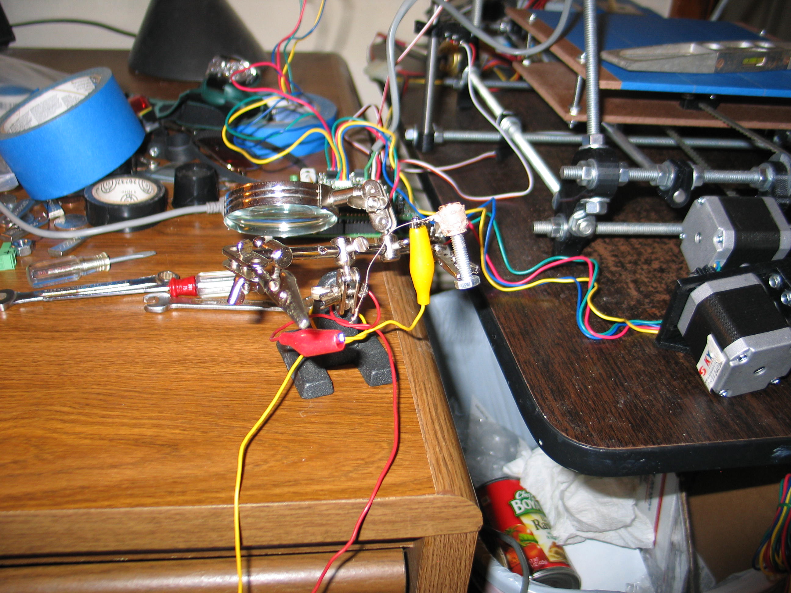
If you look at the RAMPS board in the photo above, you can see the Z axis motor plug is at an angle. I used wire I had on hand to go from that plug to the terminal block where the wires split for the 2 motors. The wire is too heavy. It's stiff and causes it to pull the plug. I need to replace it when I tidy up the wiring.
Anyway, this brings us to the end of the Prusa Mendel Visual build instructions. Don't worry, we are still a long way from our first good print!
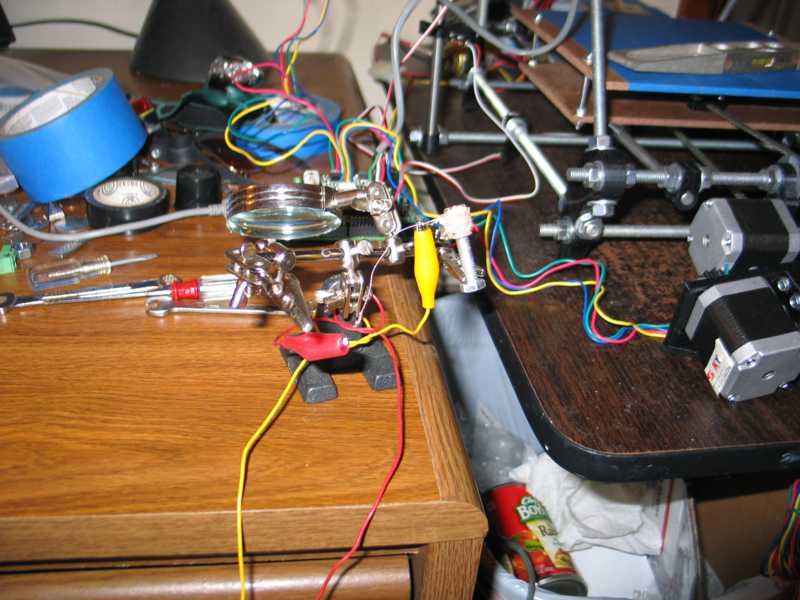
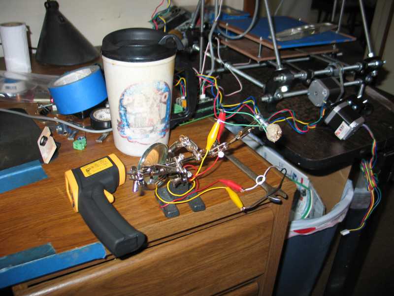
I dug out the hot end kit from Makergear. Following the instructions on their site I wound the Nichrome wire around their brass guide and slathered on the ceramic paste (fireclay?) and wired it up to 12 volts from the power supply and cooked it.
Then I did the other direction the same way.
That was too easy! I must have screwed something up. I think the platform has to be leveled more precisely when you start printing.
If you look at the RAMPS board in the photo above, you can see the Z axis motor plug is at an angle. I used wire I had on hand to go from that plug to the terminal block where the wires split for the 2 motors. The wire is too heavy. It's stiff and causes it to pull the plug. I need to replace it when I tidy up the wiring.
Anyway, this brings us to the end of the Prusa Mendel Visual build instructions. Don't worry, we are still a long way from our first good print!
I dug out the hot end kit from Makergear. Following the instructions on their site I wound the Nichrome wire around their brass guide and slathered on the ceramic paste (fireclay?) and wired it up to 12 volts from the power supply and cooked it.

Then I added the green PTFE
hookup wires. These wires are extremely fragile. They look to be
aluminum. The PTFE insulation us very tough. I had to cut it with a
hobby knife. The first time, I cut through the wire, as well.

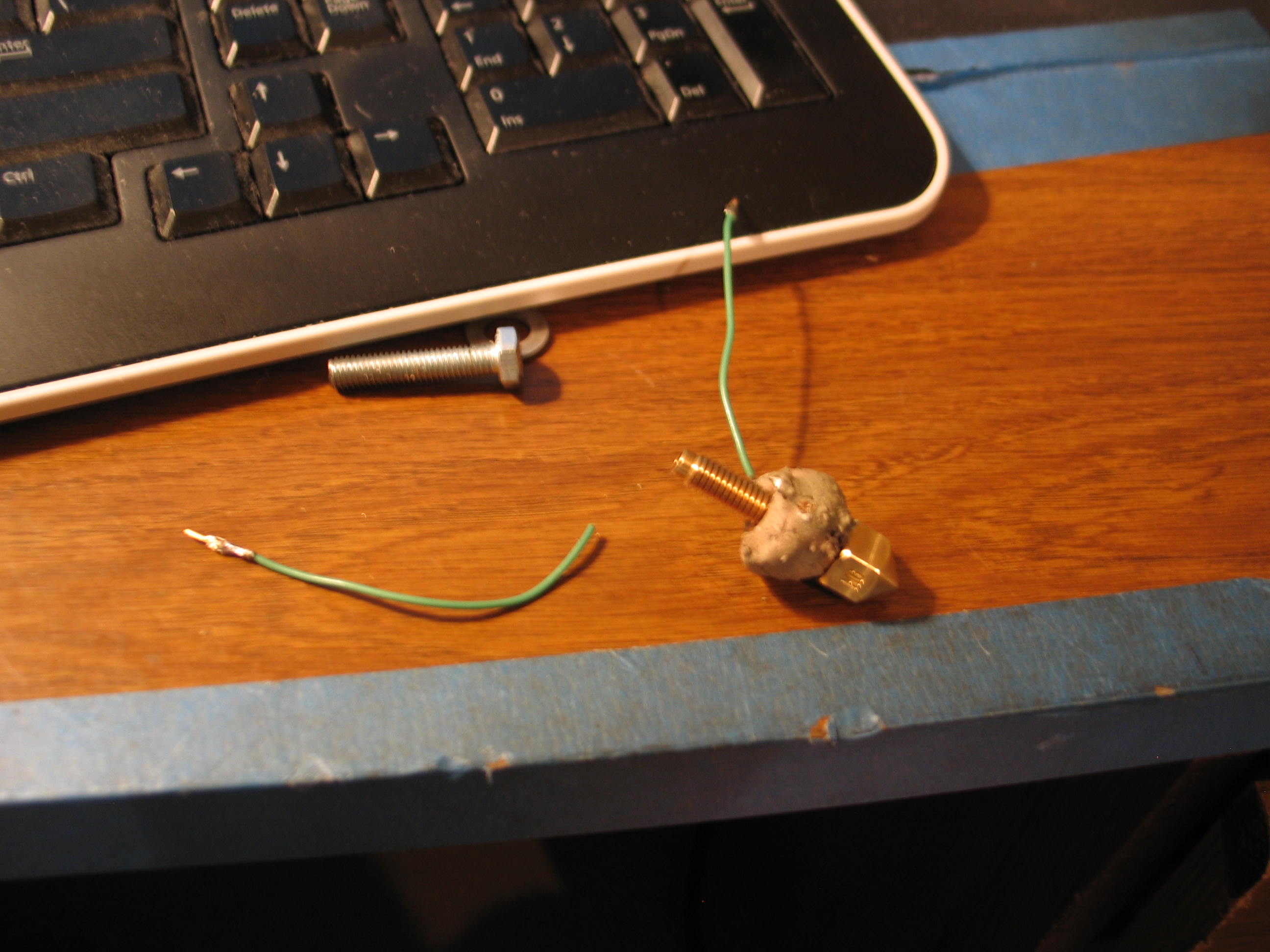
After applying the second coat of clay, I thought I was home free when one of the wires broke off! I thought I would have to trash it and start over, but I was able to chip away enough clay to solder the wire around the crimp connector. Only time will tell if it will hold. The kit comes with enough extras to make two of these ceramic cores.
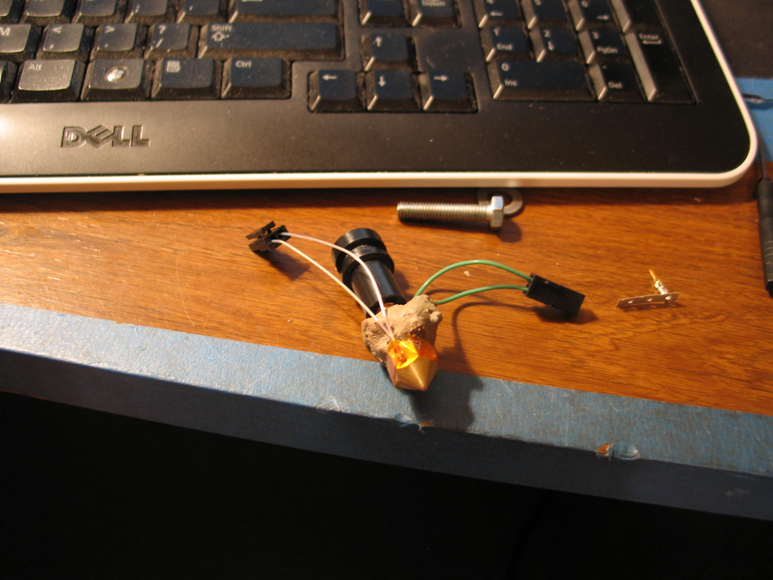
I spread some more clay and fired it again. It seems OK. The next problem was my fault. I soldered the little pins for the Molex plug on the green wires. This made them too large to go in the housing. I had to cut them off an crimp on some spares from the kit.
I also had to look up the connectors by the numbers on the tiny housings to get the data sheets for assembly details. I sure didn't want to screw these up!
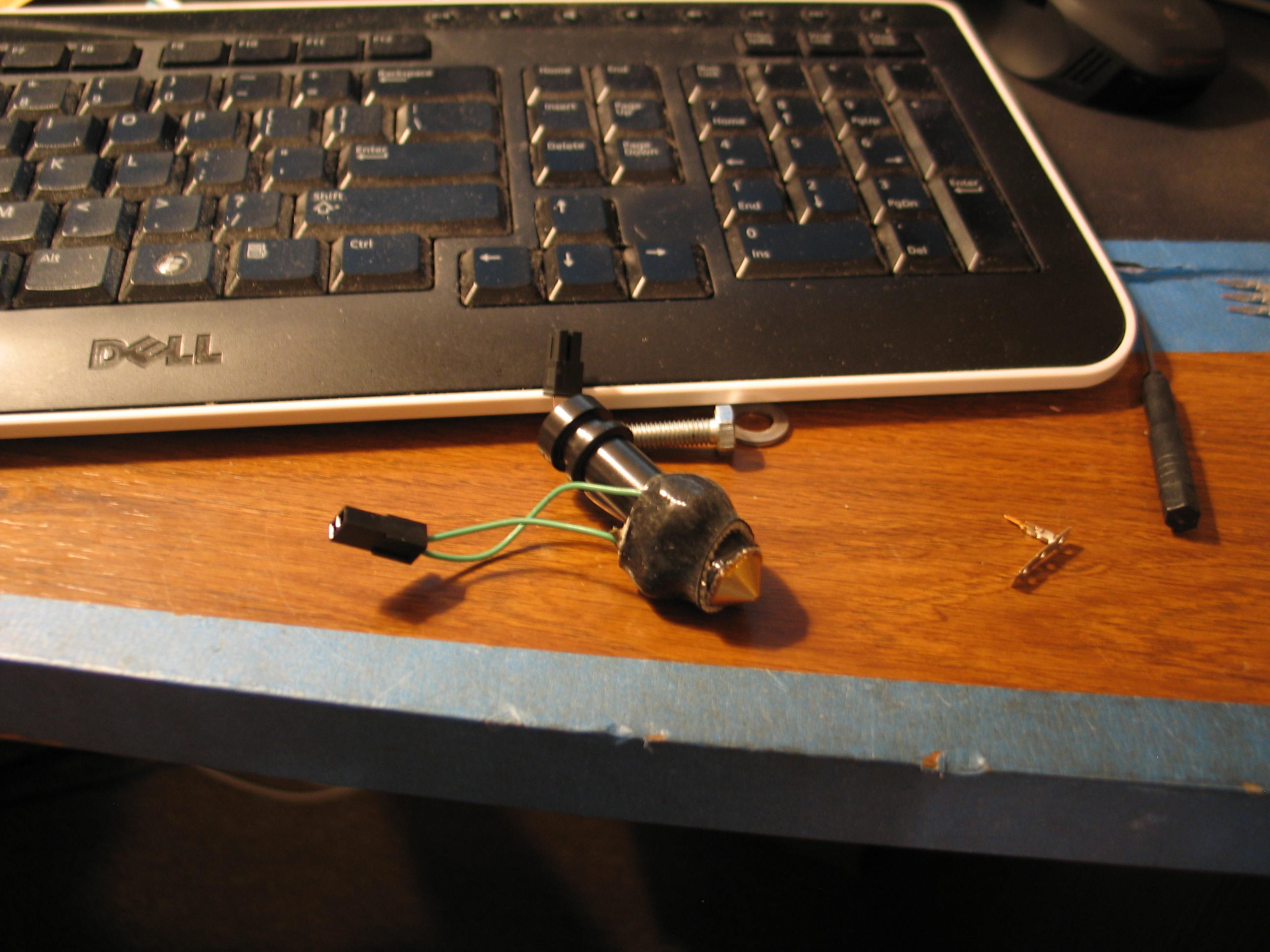
Here it is with the insulation in place. This was tricky until I stretched it over my fingers to loosen and warm it up.
My
handy dandy wooden adapter made from the DXF didn't fit. The screw
holes were off. I took a drill and wallowed out the holes. Hey, it's
just a spacer, and I an getting anxious to get this going! Excitement
is creeping in.

I had to substitute longer mounting bolts to make up for the spacer.
I don't want to quit but I'm out of time for today. I feel like I made some good progress.
I still need to wire the hot end to the electronics, and button up the wiring. Nobody seems to show you how to keep the wires out of the mechanisms, so I'll have to address that.
I hope to smell hot plastic tomorrow!
Navigate
in this series
First
Previous
Next
Last
Please leave a comment on the bottom of the page. Was this useful? What would you like to see different? Thanks.