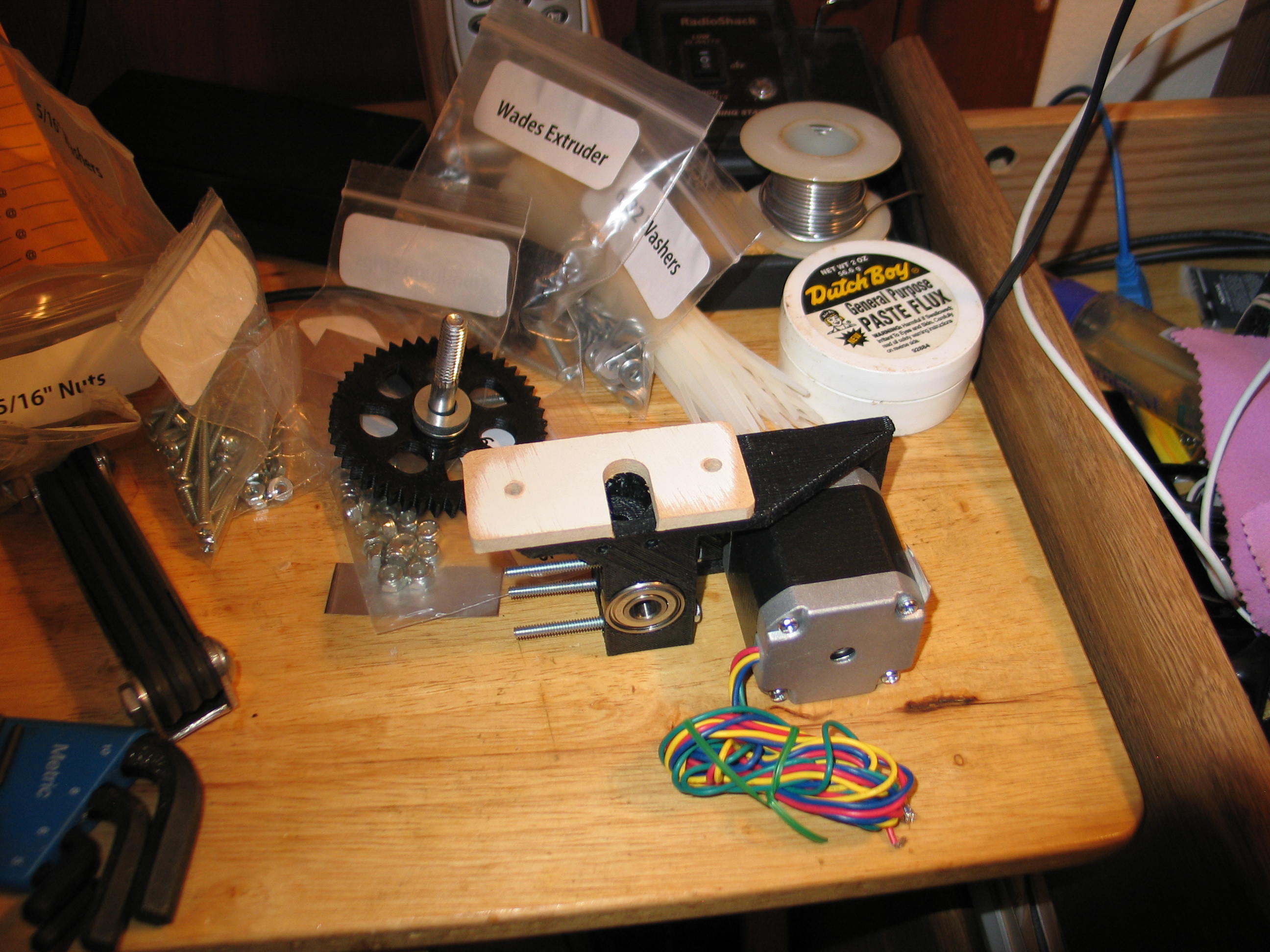
Just a little more on the extruder before we move along to wiring. I noticed the extruder didn't seem to fit the X carriage very well. The large gear was in contact with it. After some questions back to Lulzbot, I found out there is a part not shown in the visual instructions.
There is a spacer. actually a mount for the hot end. I contacted Makergear, as I ordered their hot end, and they sent me a dxf of the profile and said it was made from 1/4" plywood that actually measured about 4.7MM. I looked around and found some fan blades from a ceiling fan. They were the right thickness and were made of hardboard (Masonite).
This is how a machinist does wood working.<GRIN>
After trimming on the bandsaw and a quick hit on the belt sander, it looks like the first photo. I'll have to wait a few days for the hot end kit to see if it fits.

After trimming on the bandsaw and a quick hit on the belt sander, it looks like the first photo. I'll have to wait a few days for the hot end kit to see if it fits.
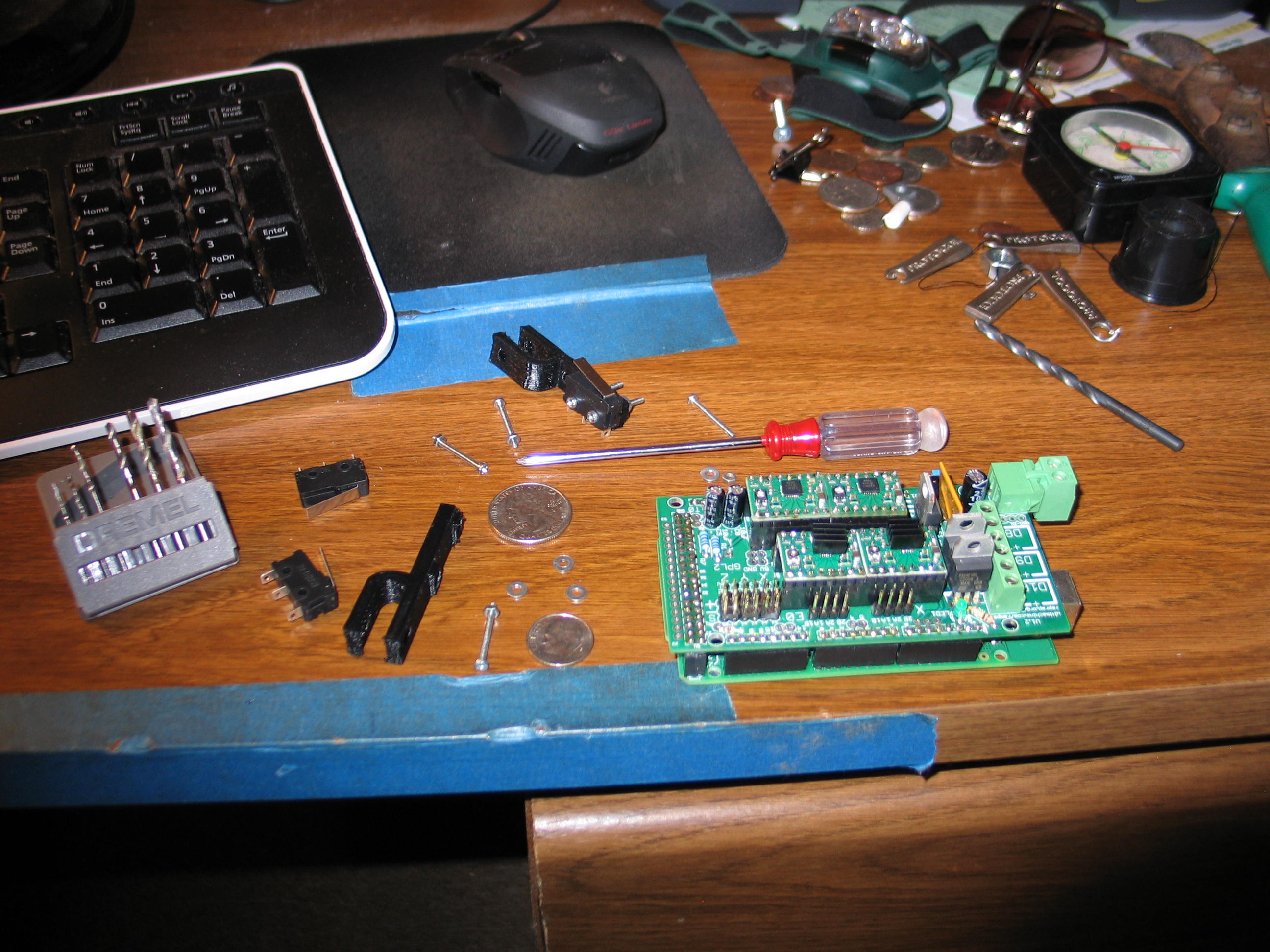
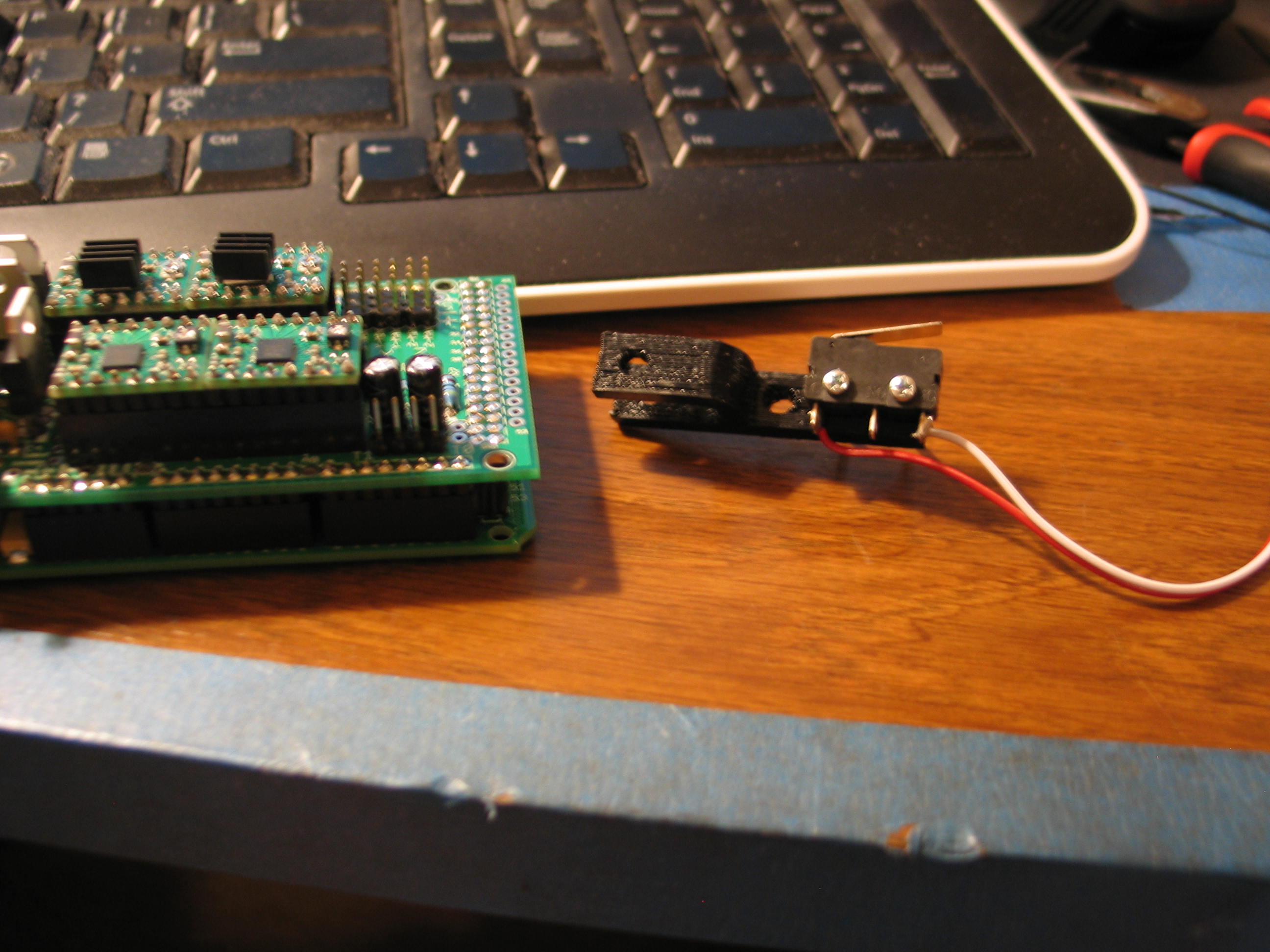
I chose mechanical switches
for the end stops. Cheaper, and I had some on hand. If they prove
inadequate, I can always upgrade later. These switches are pretty
small. They are part number A-5047 from Tayda electronics.
At 27 cents each, I bought a few on a previous order. Tayda is in
Thailand, so it takes a while for shipping, but it's hard to beat their
pricing.

The switch mounting holes are small and don't match the spacing of the printed mount. I bought 2MM hardware to mount them.
I put the end bolt in and then drilled the other one. A very easy operation, just watch those fingers!
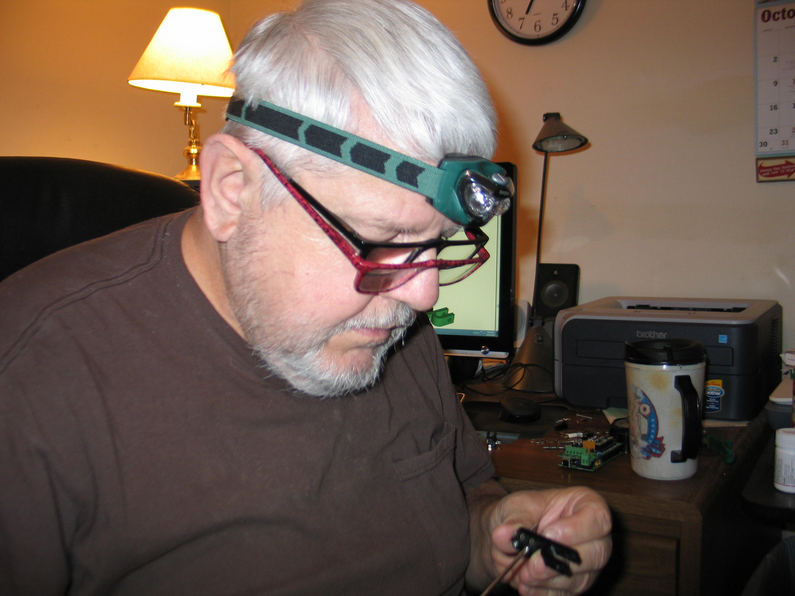
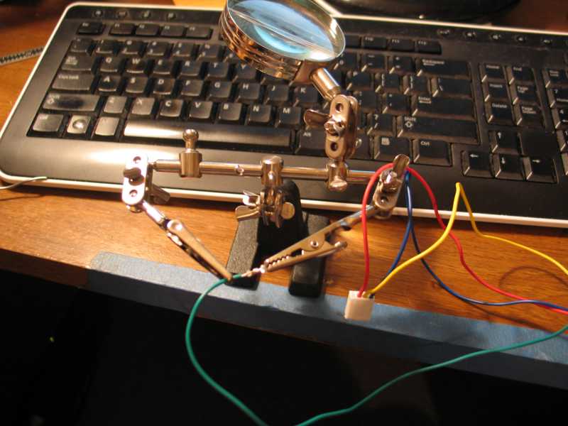
You've heard of a belt and suspenders, but have you ever seen two pairs of reading glasses? When your done laughing, try it. The LED headlight is pretty handy, as well. It's so bright, I had to turn it off for the photo.
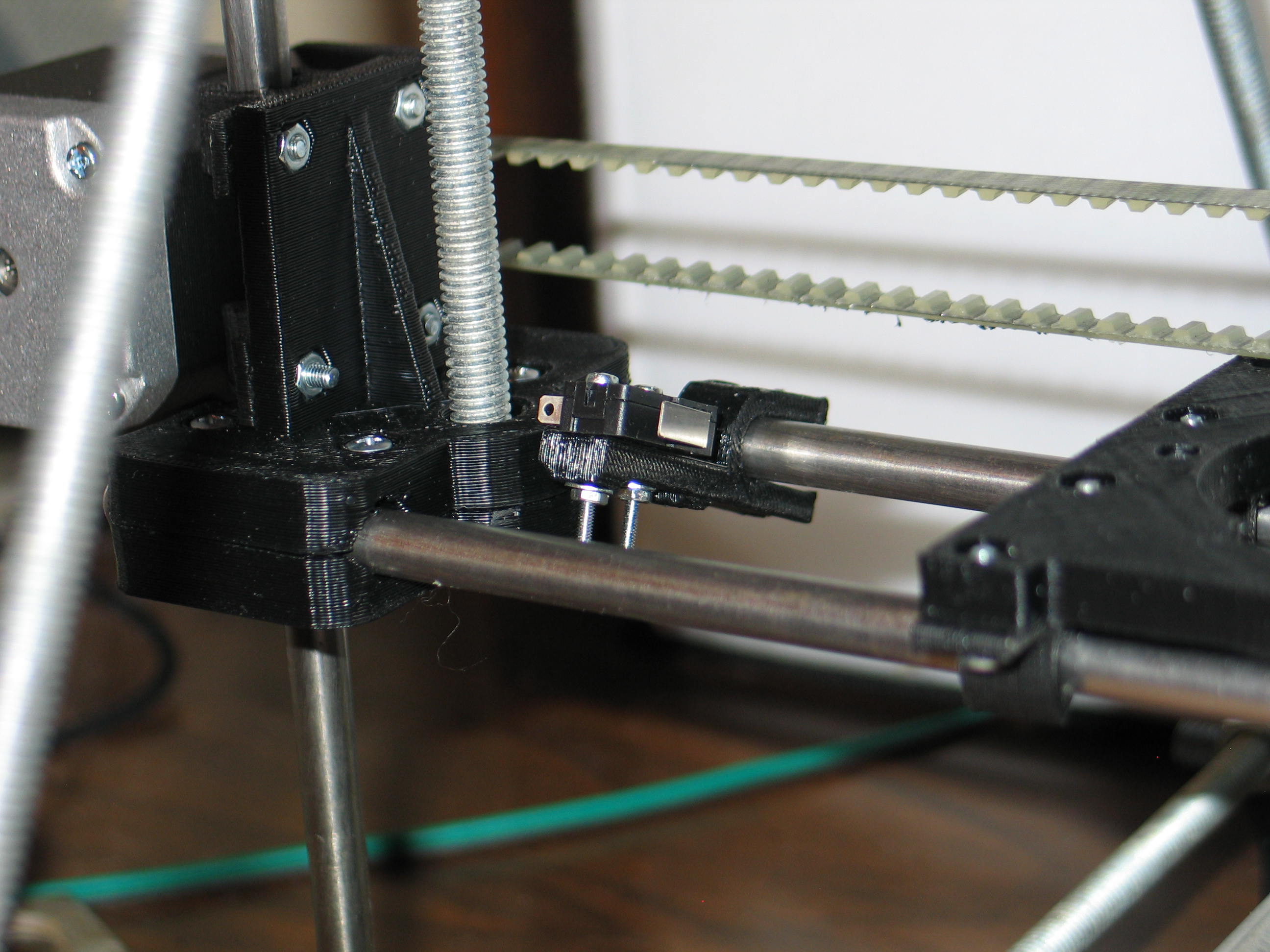
And the test fit looks good.
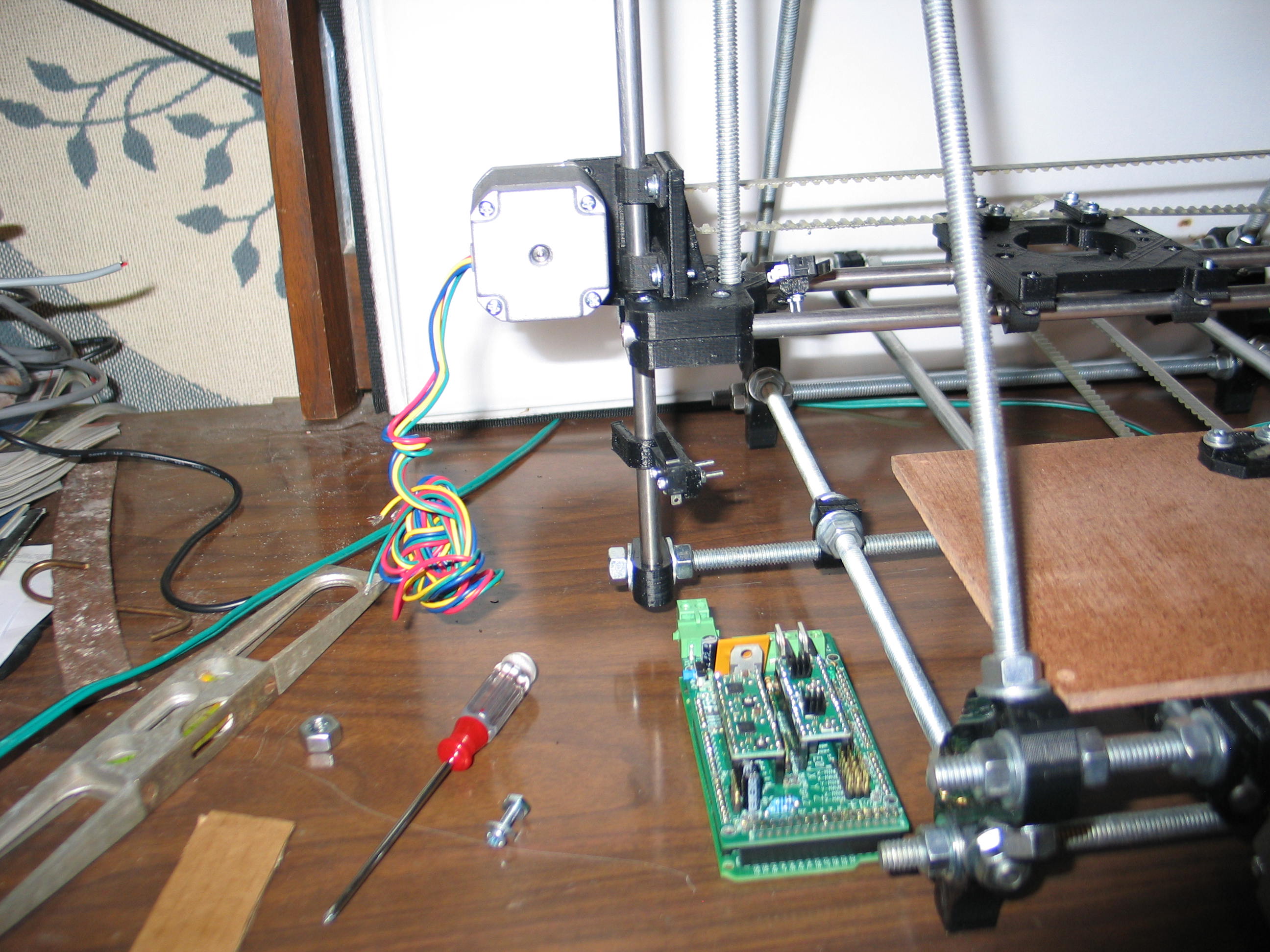
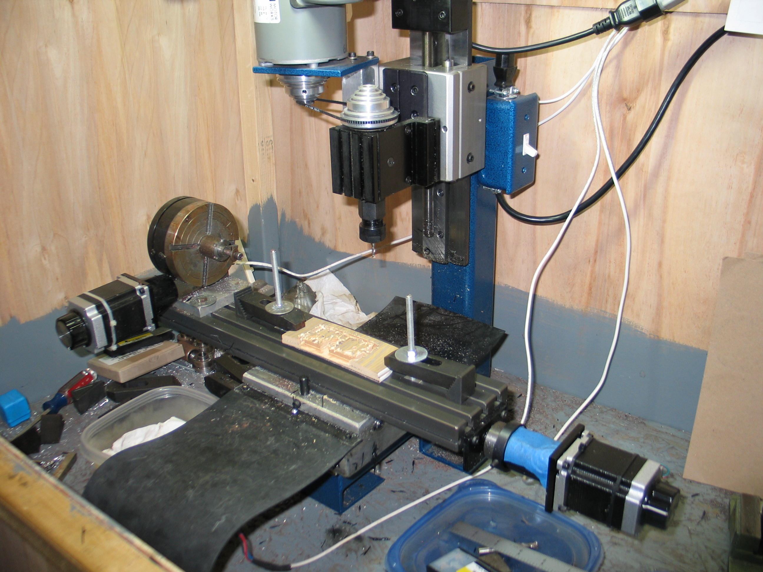
Deciding where the electronics should live.
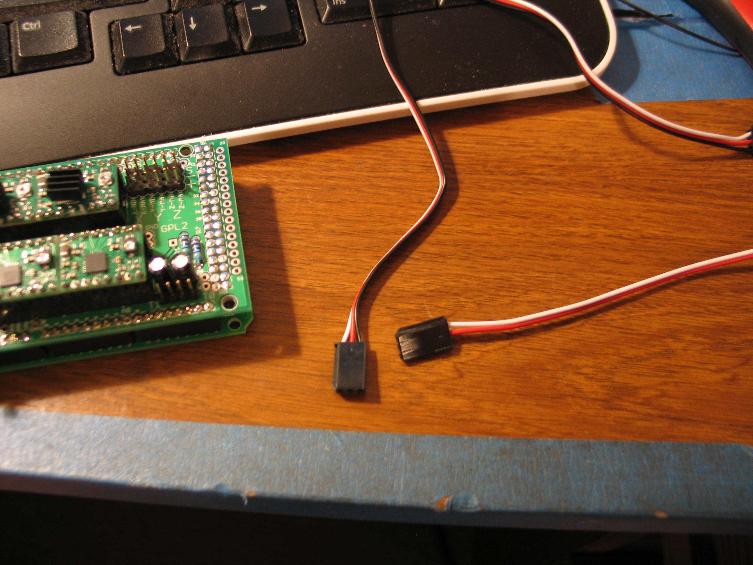
For the wires to the switches, I chose to use parts from the Radio Control world. These are 3 wire extensions for airplane servos. I linked to these as an example, they come in different lengths. Again, I had these on hand.
I
trimmed the female connector and the unneeded wire and soldered it on.
If it turns out to be too short, I can just add an extension!

The left one is uncut, the right has the black wire removed. Damned shadow looks like the wire.

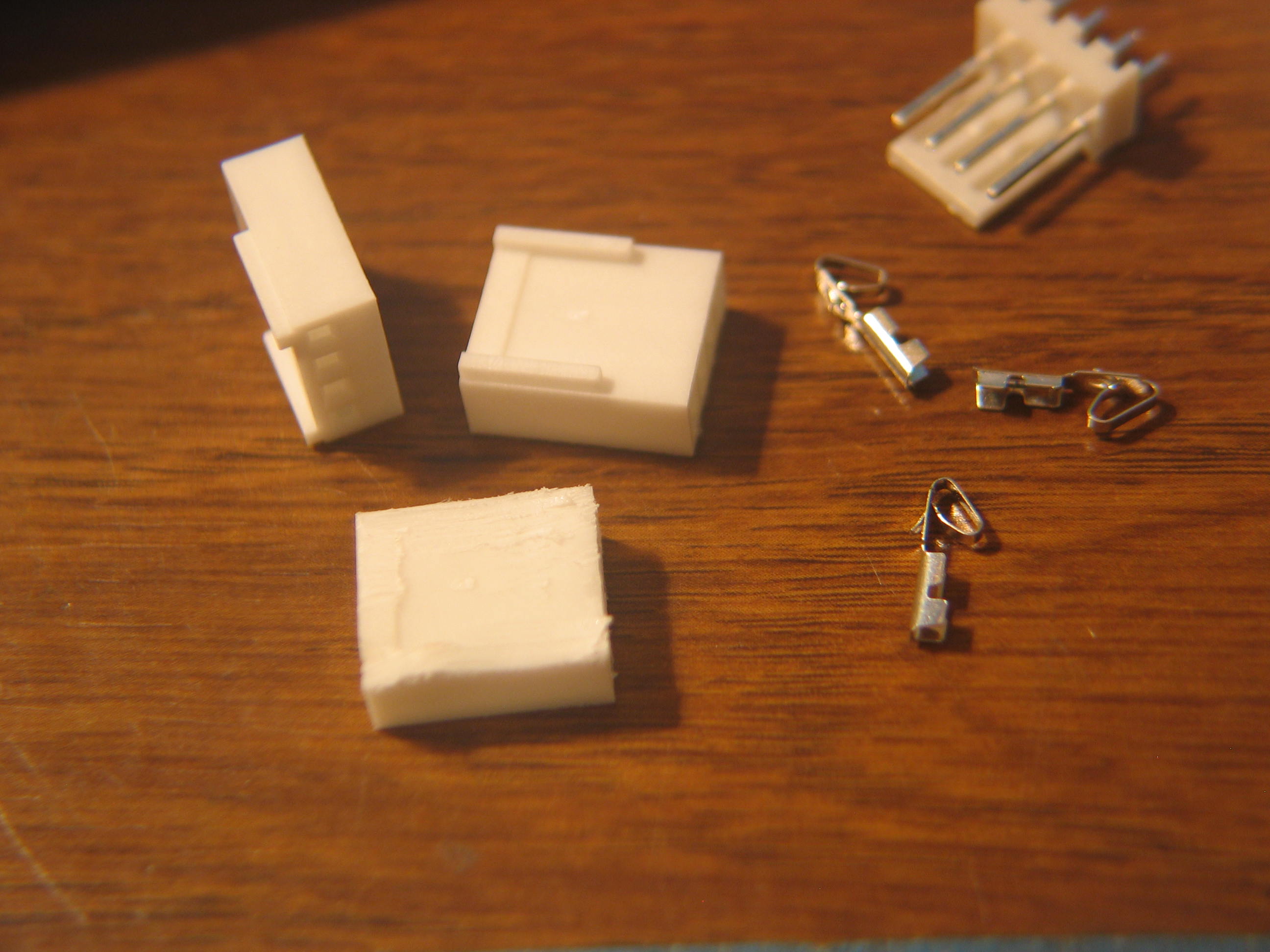
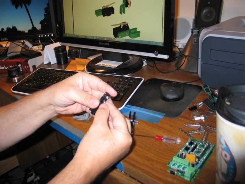
I had these 4 wire connectors as well. Just right for the motors except for the pesky shoulders that get in the way.

It's hard to see, but the housing is held firmly in a Panavise jr. You could also use a hobby knife or a soldering iron.
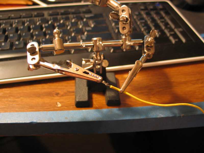
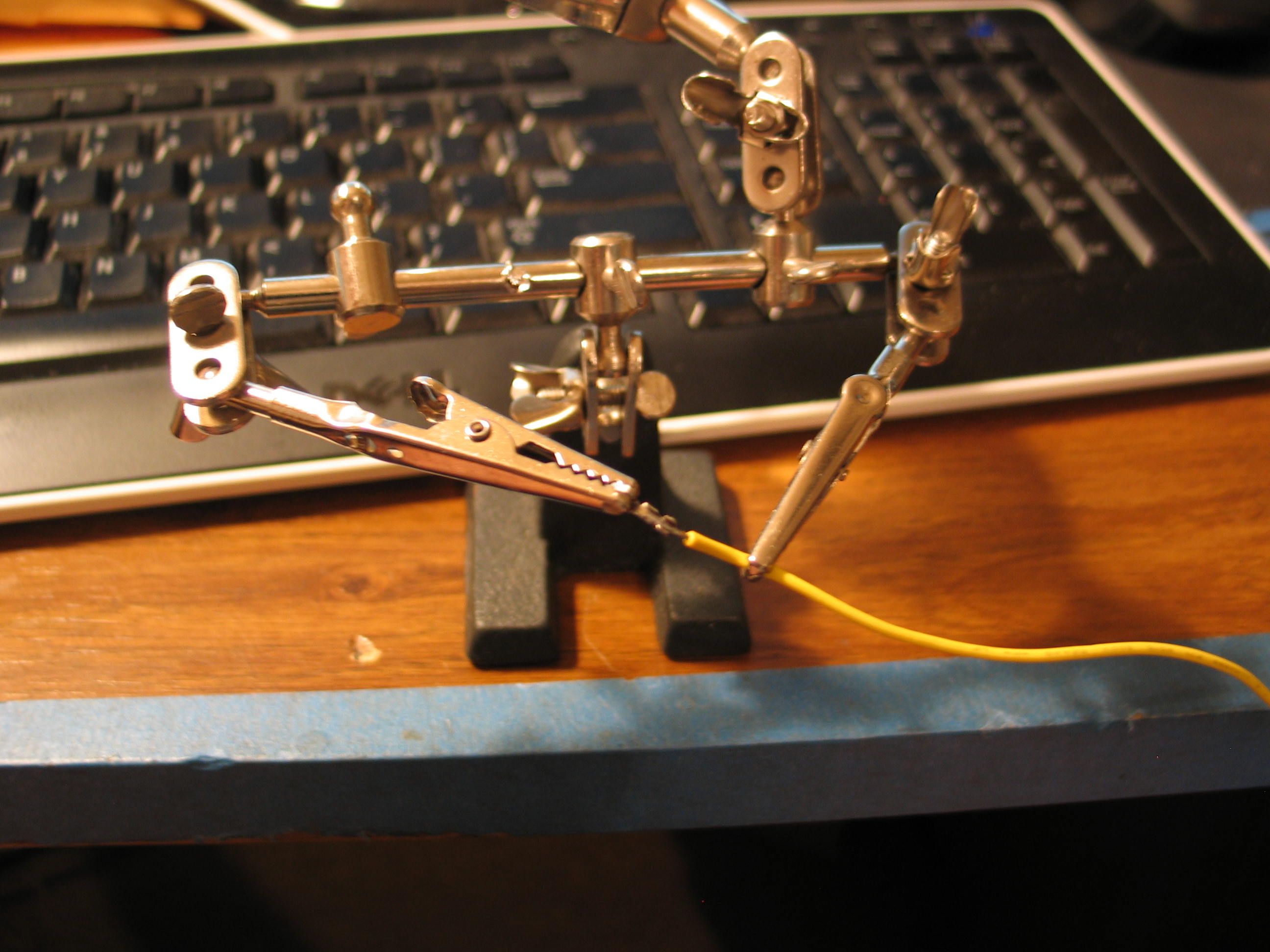
I
don't have the crimping tool for these little pins. I crimped three
with needle nosed pliers before I screwed up two in a row. Soldering is
easier.

Once
attached to the wires, the pins just push into the housing. Be careful
to get them in the right order. It's possible to get them back out, but
it's hard unless you have the right tool.
My steppers didn't match the color chart on the RAMPS 1.2 page, and I found it to be ambiguous. 2A, 2B, 1A, 1B. Are the As a coil or the 1s?
I had to reach back to the Pololu ducumentation and then to the driver chip data sheet to be sure. It turns out the number is a coil, as in 1A, 1B equals A and A not.
Clear as mud?
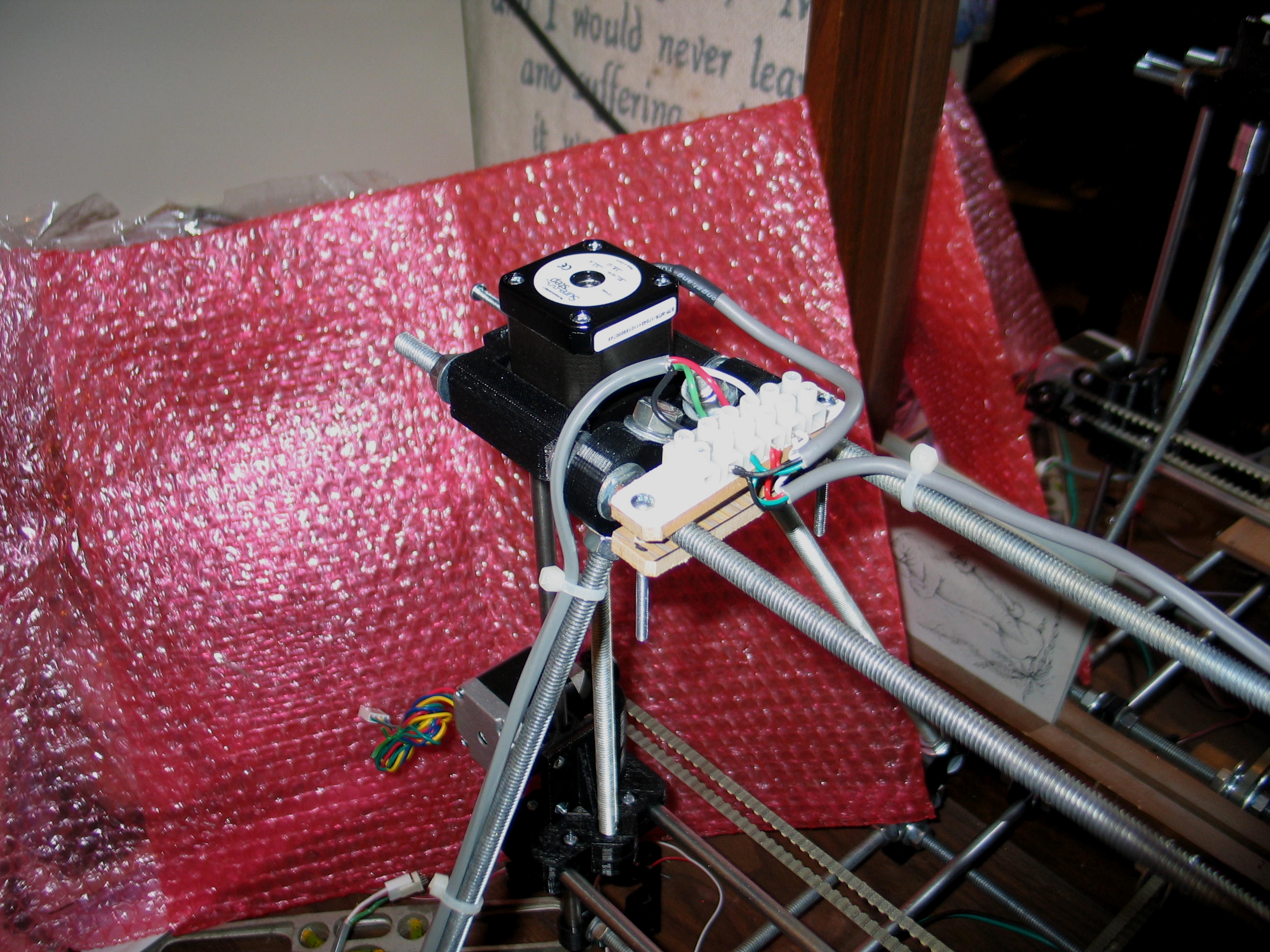
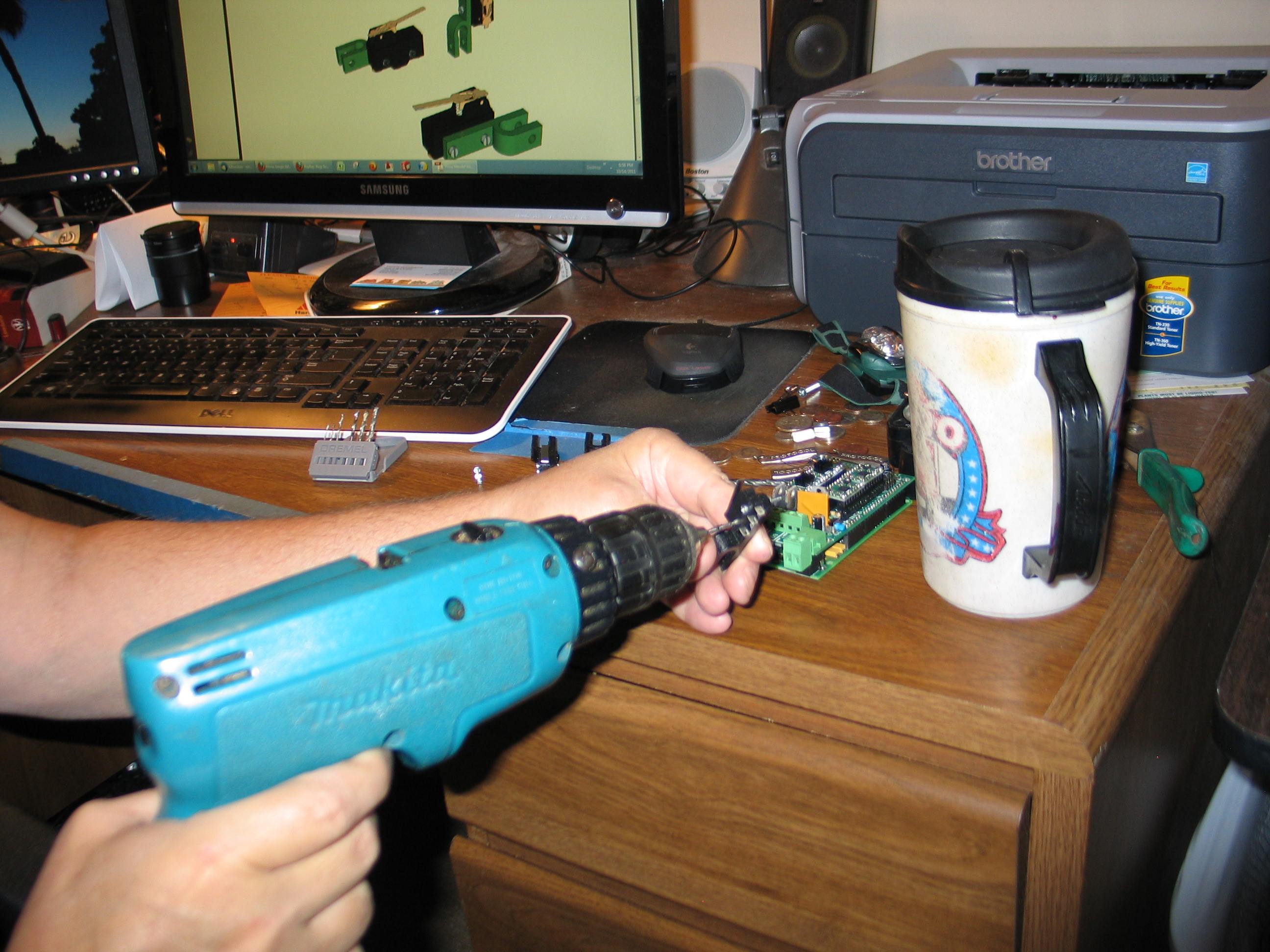
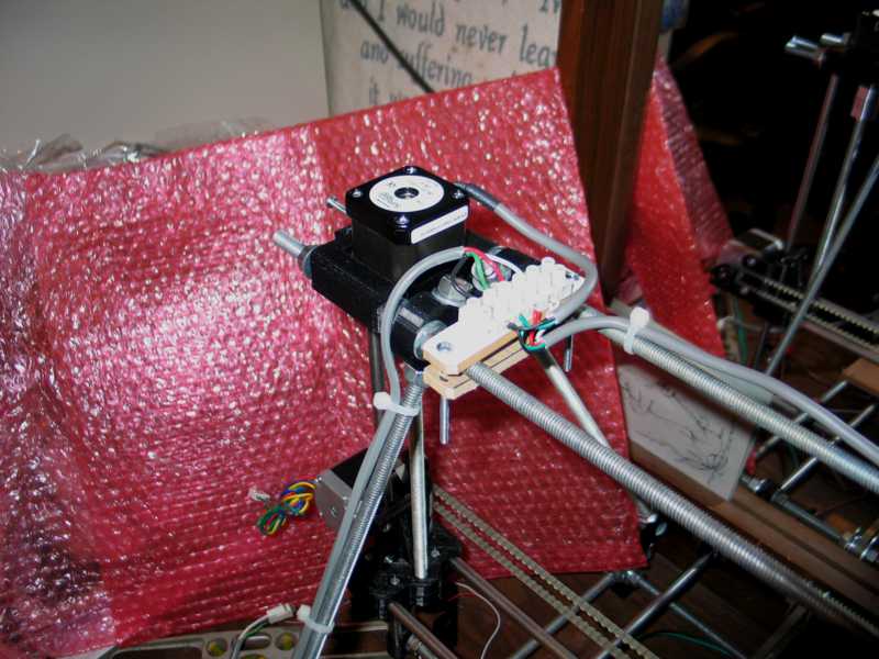
One
of the design features that seems iffy is the two Z axis motors are
wired to one driver. The wires are paralleled at this screw terminal.
There are lots of Prusa Mendels out there, so it must work.
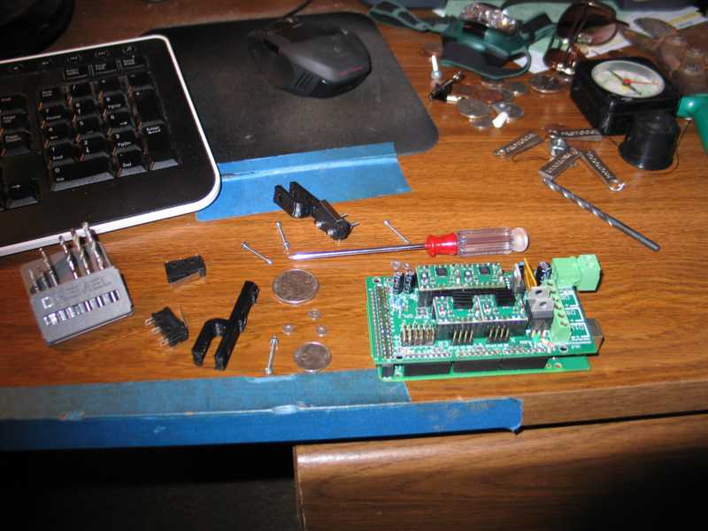
I used two pieces of hardboard to make the mount for the terminal.

This is what it looks like at this point. I used a multimeter to check all the wiring as I went.
Next time, power supply, plug everything in and hope for no smoke!
I used two pieces of hardboard to make the mount for the terminal.
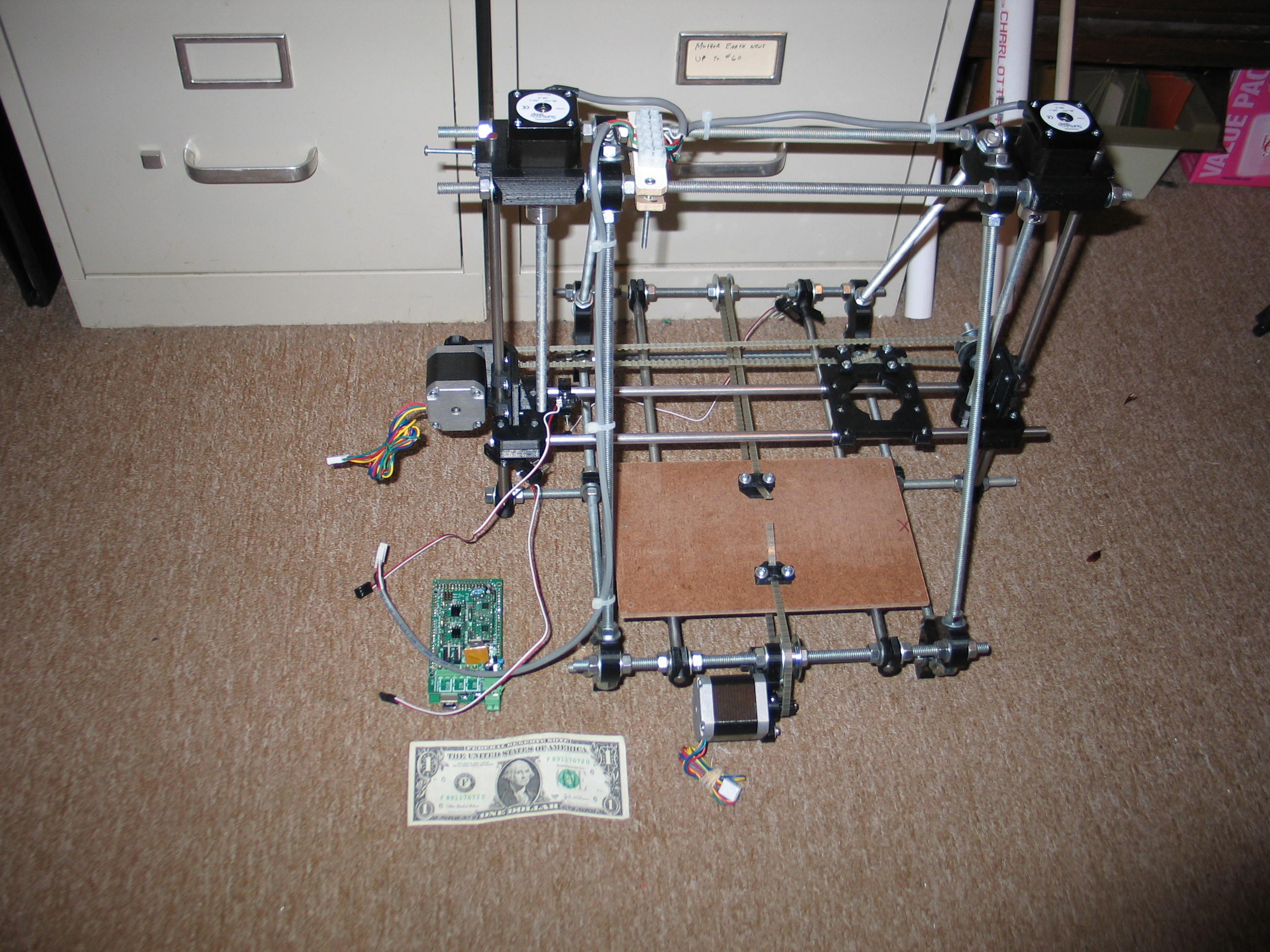
This is what it looks like at this point. I used a multimeter to check all the wiring as I went.
Next time, power supply, plug everything in and hope for no smoke!
Navigate
in this series
First
Previous
Next
Last
Please leave a comment on the bottom of the page. Was this useful? What would you like to see different? Thanks.